 Pristupačnost
Phase I (Starting date 10/5/2019 - principal engagement in Croatia before the start of the visit)
Task I.1 Literature review
Investigation of modelling techniques in case of spot welding in finite element software ABAQUS in case of cold-formed steel elements has been carried out. In order to obtain realistic results from the finite element nonlinear analyses, plastic strains were included in the material definition, according to EN1993-1-5, Annex C.
The spot weldings (SW) between different parts of the built-up beams have defined the function of the tensile-shear tests of the simple specimens as follows. Attachment points were defined on each part where SW was applied. The connection between the attachment points was defined using Point-Based Fasteners with the Connector response of the SW initially calibrated from the tensile-shear test results.
The geometric and material non-linear analyses including the effects of initial imperfections (GMNIA) was used. FE models have been calibrated in accordance with the experimental results of input parameters such as experimentally measured properties of materials and tensile-shear tests on the lap joint welded specimens. Each part of the built-up beam has been defined as a 3D shell element extruded according to the shape of the part. Rectangular 4-node doubly curved thin or thick shell, reduced integration, hourglass control, finite membrane strains (S4R) were used to model the thin-walled components. The global mesh size of 15 mm was used.
Calibrated numerical model in ABAQUS with thicknesses of components is shown in Fig. 1.
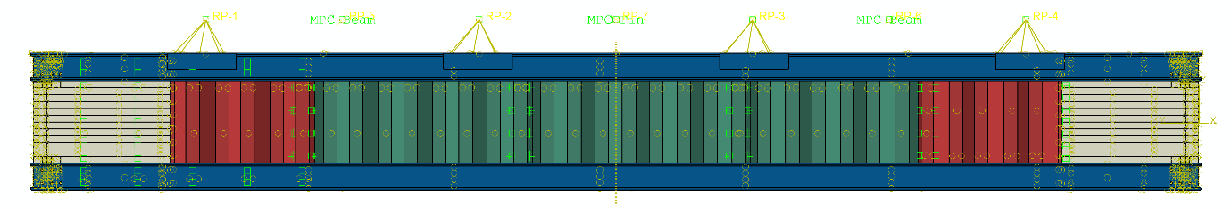
Figure 1. Thicknesses of the CWB SW-1 beam by components: blue 2.0 mm (flanges), grey 1.0 mm (shear panels), red 1.2 mm (webs near supports) and green 0.8 mm (mid-span webs)
Phase II (during the visit: from 20/6/2019 to 20/7/2019: 31 days)
Task II.1 Preparation of specimens for experimental research
Testing set-up, instrumentation and testing protocols have been prepared for two specimens with web openings based on the previous tests. The built-up beams were tested in a planar rigid frame with both ends fixed to the frame. A 500 kN actuator loaded the beam through a leverage system that uniformly distributed the load in 4 points in order to simulate a uniform distributed load.
Compared to the previous built-up CWB without web openings, for which the web consisted of individual corrugated panels of approximately 1 m, the web of the current specimens was made of a single piece, i.e. a continuous web. Thus, the built-up of the beams consisted in three stages: 1) connecting the shear panels to the corrugated web, 2) connecting the flanges to the web and 3) connecting the supporting device to the beam.
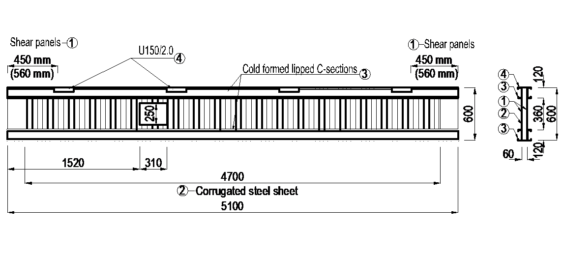
Figure 2. Components of CWB specimens (all dimensions in mm).
The beams consisted of the following components: (1) corrugated steel sheet for the web - 1.0 mm; (2) additional shear panels - flat plates of 1.2 mm; (3) two back-to-back lipped channel sections for flanges - 2 × C120/2.0; (4) reinforcing profiles U150/2.0 used under the load application points; (5) bolts M12 grade 8.8 for flange to end plates connections, as presented in Figure 2.
Similar welding techniques used for the built-up beam were considered also for the reinforcing solution of the web opening. In order to apply the welding, different configurations were selected. For the beam built-up by spot welding, a 2.0 mm thick flat steel plate was welded on the contour of the opening, with the dimensions given in Figure 3. Only one reinforcing plate was used due to the limited possibility of welding another plate on the opposite side of the corrugation. The reinforcing plate was also bent to 90o on both sides parallel to the flanges. These lips were also spot welded to the flanges. The undeformed shape of the built-up beam in the experimental stand is presented in Figure 4.
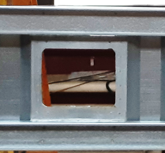
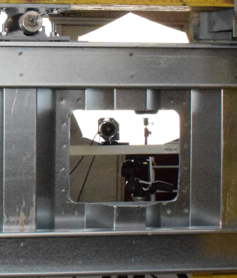
Figure 3. Reinforcing the web opening of the CWB-SW-WO specimen.
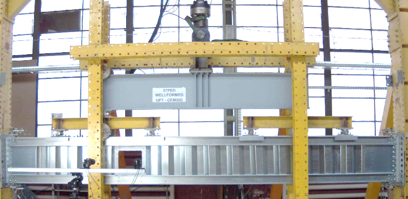
Figure 4. CWB-SW with web opening specimen.
A convenient configuration for the reinforcing of the web opening was performed for the CWB specimen built-up using MIG brazing. A 1.2 mm steel plate was bent in order to take the shape of the web opening. Since the corrugation height of the web was 45 mm, a wider plate was necessary to allow the MIG brazing. Also, to facilitate the insertion, the reinforcing plate was conceived by two U shaped pieces of 80 mm width. For the side parallel to the flanges, the brazing was performed alternatively on each corrugation, while for the vertical sides the brazing was applied as intermittent segments Figure 5 presents the solution for the web opening reinforcing. The full-scale beam specimen of the built-up beam connected by MIG brazing is presented in Figure 6.
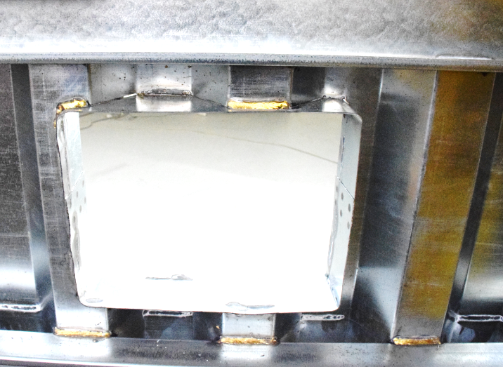
Figure 5. CWB-CMT with web opening specimen - reinforcing solution.
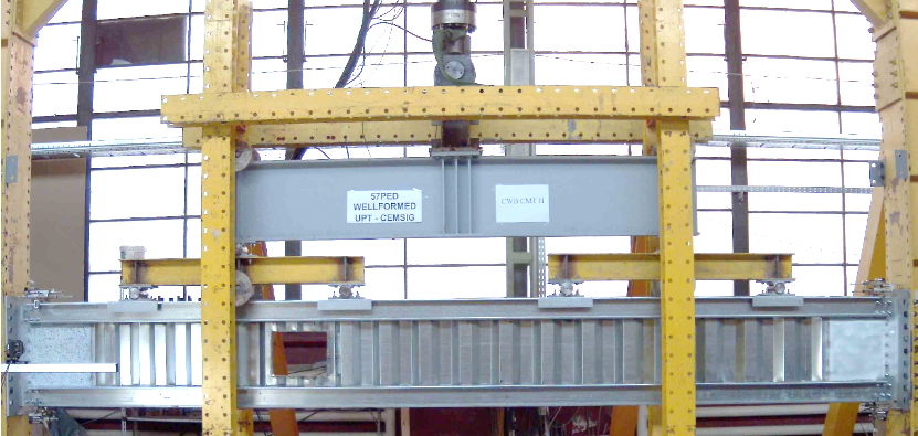
Figure 6. CWB-CMT with web opening specimen.
Task II.2 Experimental tests on two beams with web openings
The response of the beam is assessed not only by the bearing capacity but also the failure mechanism that conducted to the collapse. Starting with the general view, Figure 7 presents the deformed shape of the beam specimen built up by spot welding. A significant deformation is noticed on the left side of the web opening.
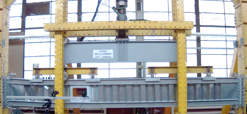
Figure 7. Deformed shape of the CWB-SW beam with web opening.
The second beam specimen, built-up by using MIG brazing, presented also an increased deflection in the web opening side but only in the last stage of the testing, see Figure 8.
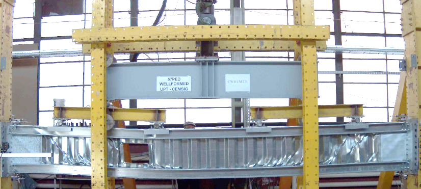
Figure 8. Deformed shape of CWB-CMT beam with web opening.
Experimental tests with web openings in beams have been used for parametric studies in case of floor systems in multi-storey buildings.
Task II.3 Calibration of numerical models and optimisation of technical solutions
Analysis of the main parameters of test results that describe the response of tested specimens extracted to serve for development, validation and verification of numerical models parameters for accurate estimation of the experimental results. Partially this part has been prepared during the preparation of the paper for Timisoara Conference based on previous test results and has been reported in Annex 1. The calibration of the numerical models and optimisation of technical solution in case of tested beams with web openings has been prepared during visit. Calibrated and validated numerical models represent bases for a parametric study which had to ensure the validation of suitability for the spot-welded corrugated web beams with cold-formed thin-walled elements, for larger spans. Additionally, numerical parametric studies investigated the suitability of this system in case of single-storey buildings
The calibrated numerical models in case of CWB beams without and with web opening are shown in Fig. 9.
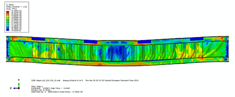
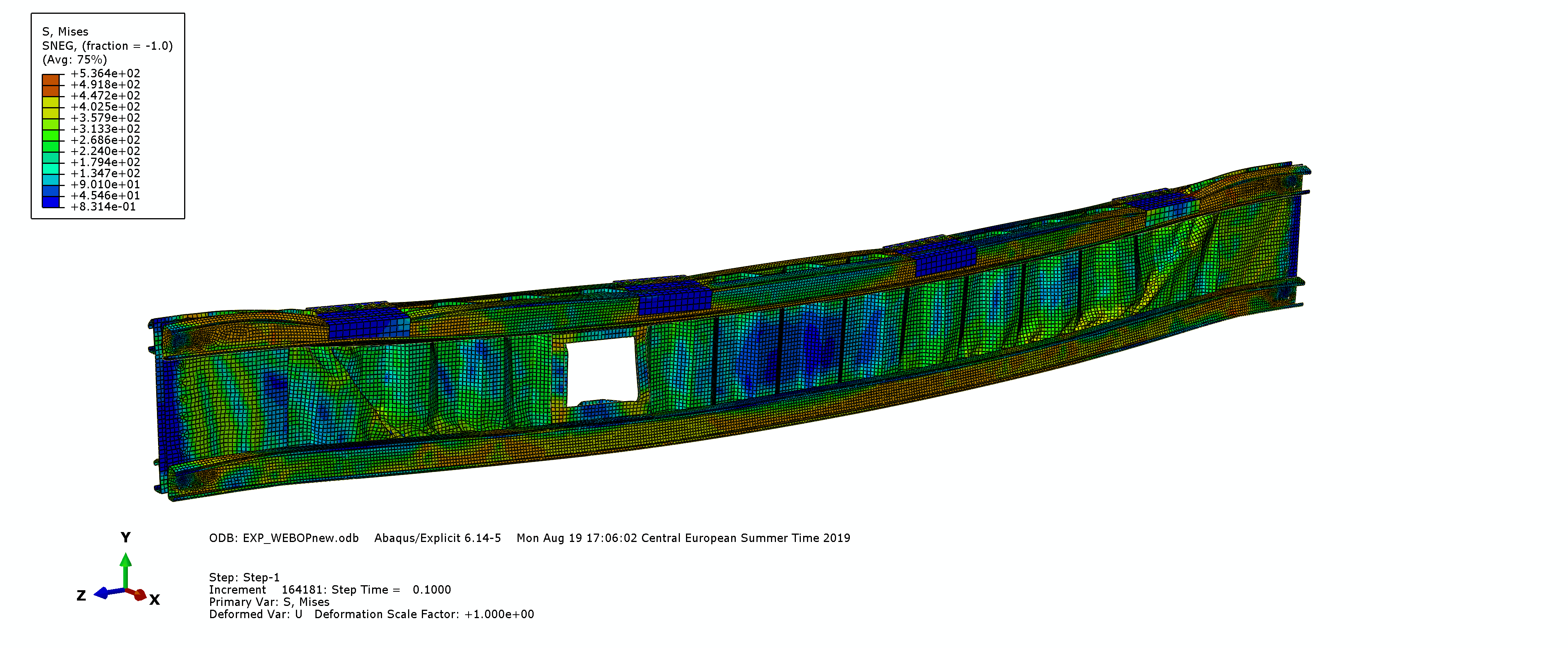
Figure 9. Calibrated numerical models without and with web opening
Task II.4 Design and numerical analysis of beam with larger spans
The verified numerical models have been used for parametric analyses varying the dimensions of the beam. Prior to numerical analyses, the analytical study of different geometries in case of beams with larger spans has been conducted. The results of an analytical and numerical study have been presented in Annex 4. Numerical model and results in case of beam 12 m spans are shown in Figs. 10. and 11.
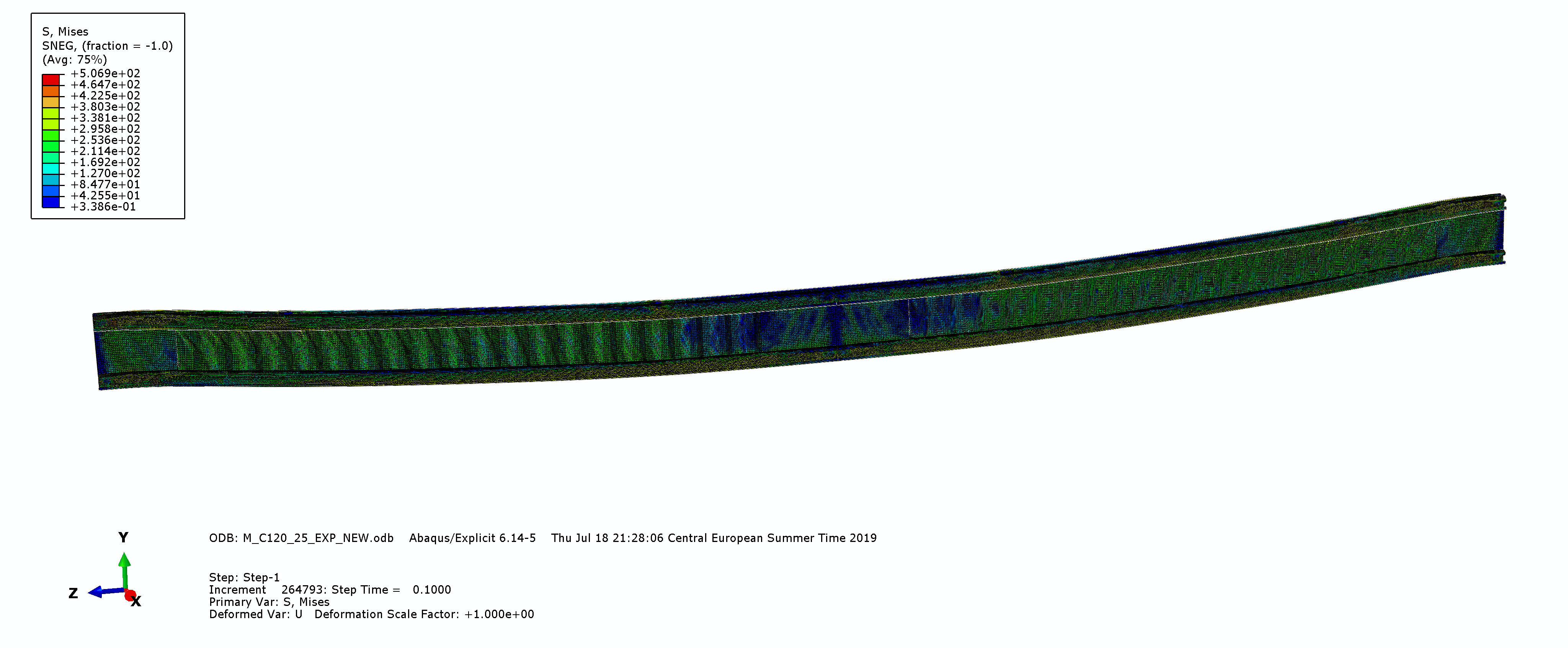
Figure 10. Numerical model in case of 12 m span
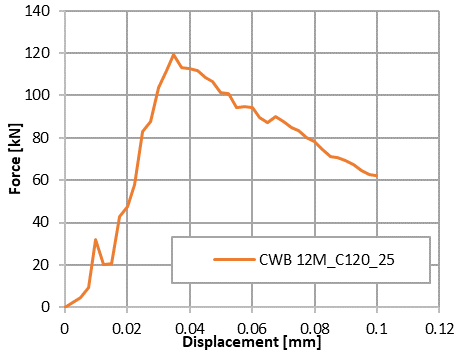
Figure 11. Results in case of 12 m span
Phase III (Target completion date 10/8/2019 - engagement in Croatia)
Task III.1 Evaluation and interpretation of results in terms of technical-economic performances
Interpretation of results consists of the processing of numerical results obtained for beams regarding the parametric study, to understand the behaviour of the beam and to identify the key parameters which govern the behaviour of such elements.
Task III.2 Exploitation and dissemination of results
Some of the project outcomes are already published trough conference paper (Conference in Timisoara) and other outcomes will be disseminated through publication in the journal paper and conference proceedings. The abstracts for conference Eurosteel 2020 and one additional conference Indian Structural Steel Conference 2020 are already submitted. It was decided to extend parametric numerical study order to gain more data for verification of analytical proposal for design recommendations.
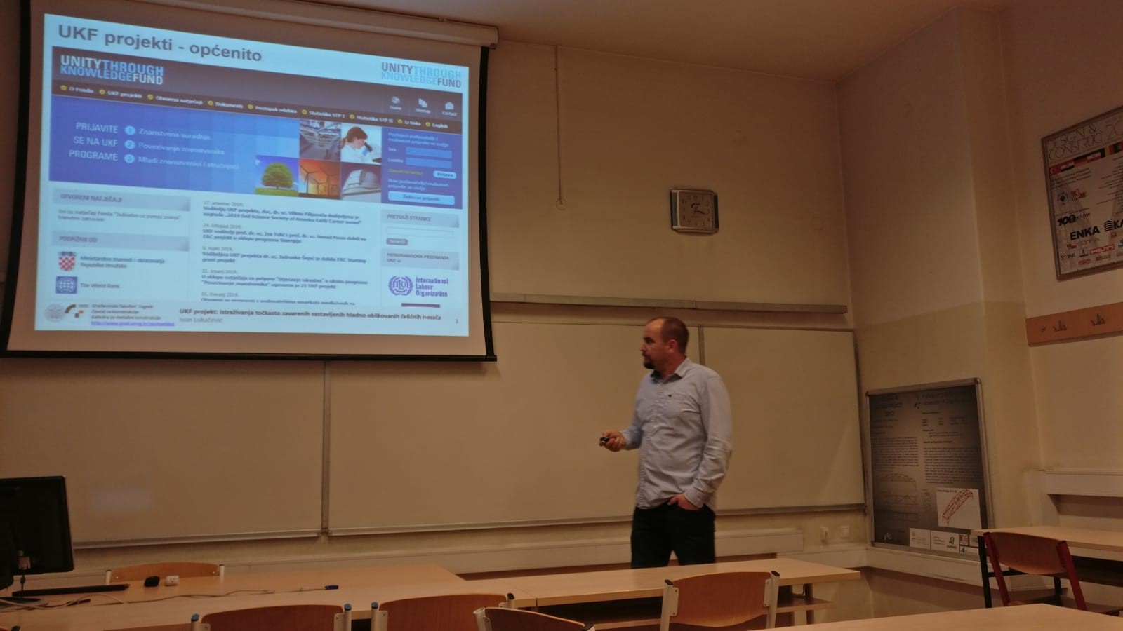
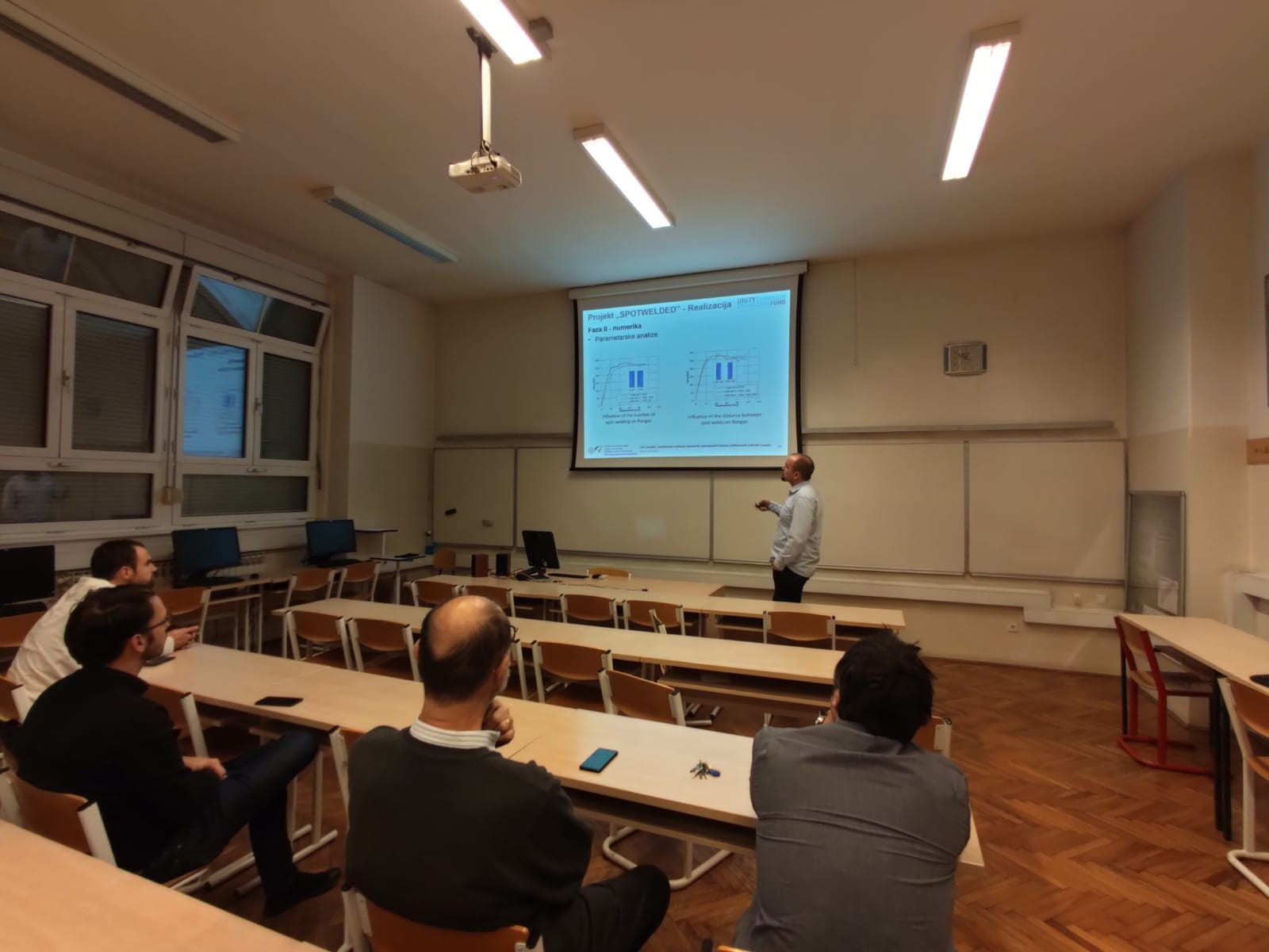
Figure 12. Presentation of the project and project results at the Faculty of Civil Engineering in Zagreb, 19. December 2019